Moving and Rotating Models
When merging multiple IFC files for coordination occasionally one or more of the files may not correctly align with the other model files. When this occurs it is advisable to have the author of these files move them into their correct locations in the native authoring software. However, if this is not an option, or if you would prefer to proceed with coordination before the changes can be made, there is a “Move or Rotate Models” capability in Solibri Model Checker (SMC).
In the example below, the Structural model is not aligned with the Architectural and Mechanical models.

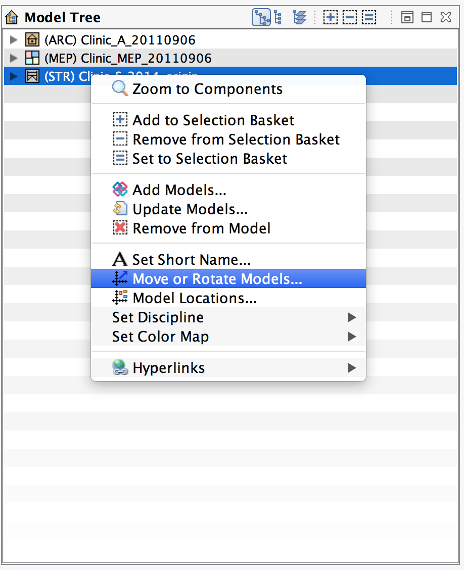
From the model tree, select the file that is misaligned with the other BIM models. Right click, and select “Move or Rotate Models”
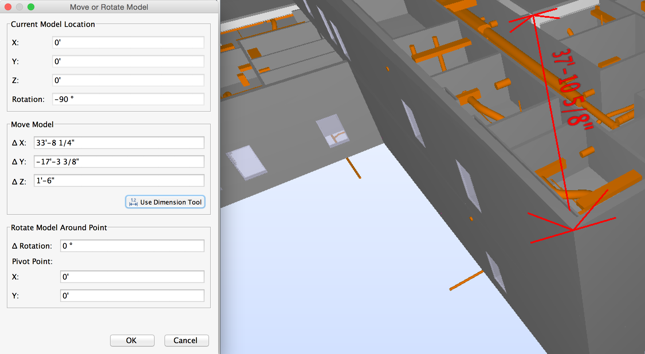
The “Move or Rotate Model” window appears.
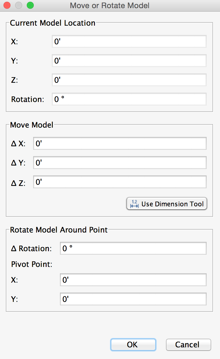
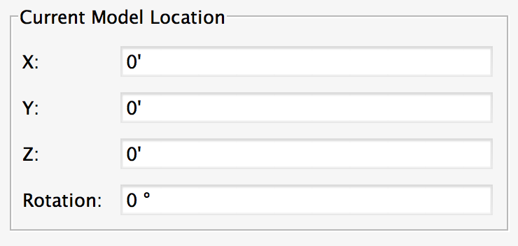
Current Model Location: This will always be 0,0,0,0 to begin. Once a model has been moved in Solibri Model Checker the coordinates will change to reflect the distances and degrees moved. This makes it very easy to reverse any changes made in SMC that may be incorrect, or to undo the move once the original BIM file has been updated.
Move Model: A user can enter a specific value for X, Y, or Z to move the model. Negative numbers can also be used. Additionally, a user can choose to “Use Dimension Tool” and move the file by aligning a point or object with a corresponding point or object in another file.
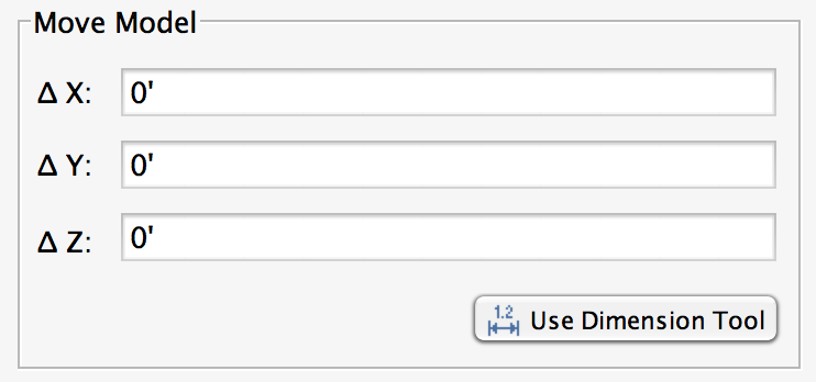
Rotate Model Around Point: The file can be rotated by degrees of rotation. A negative number will rotate the file clockwise, and a positive number counterclockwise. A user can also specify a pivot point that the rotation should revolve around.
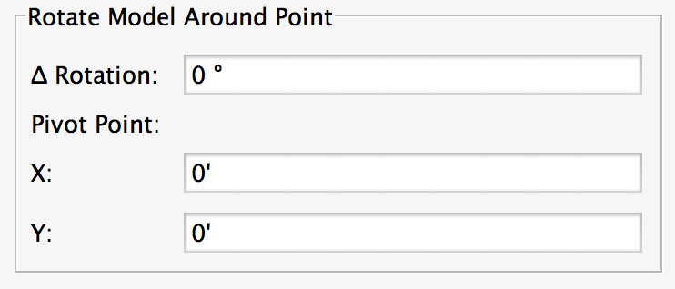
To move our model correctly, we will first try the Rotate Model Around Point option, and try to rotate it to the correct position. In this case, we can see by looking at the two models that the central lobby roofs in the Structural model are 90 degrees counterclockwise from the Architectural curtain walls they should be joined to. Therefore, we will rotate the structural model -90, or 90 degrees clockwise.
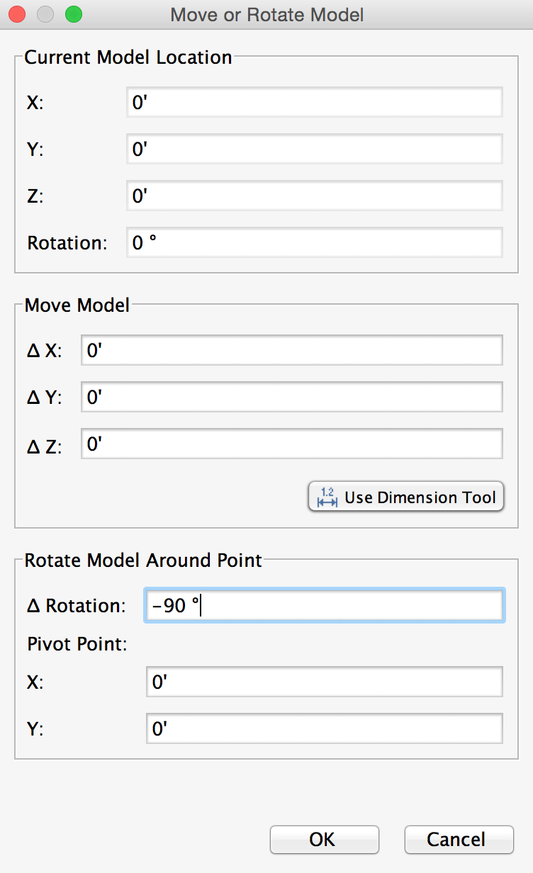
After doing this, the structural model now appears to be correctly aligned. In these situations, it is often the case that the rotation will be off by either 90 or 180 degrees from the modeling software, so if it isn’t as obvious as in our example, those are still good starting points.
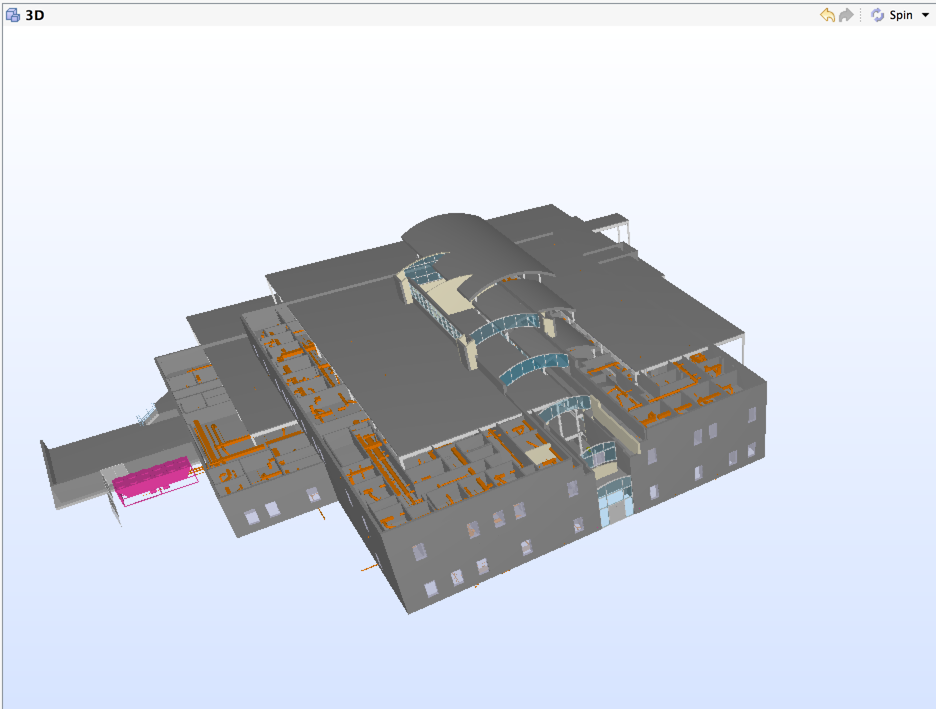
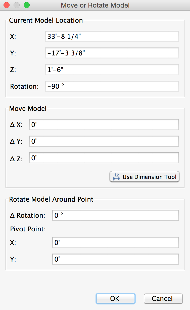
From here, return to the Move or Rotate Models window. Note that the Current Model Location shows we are now located at -90 degrees.
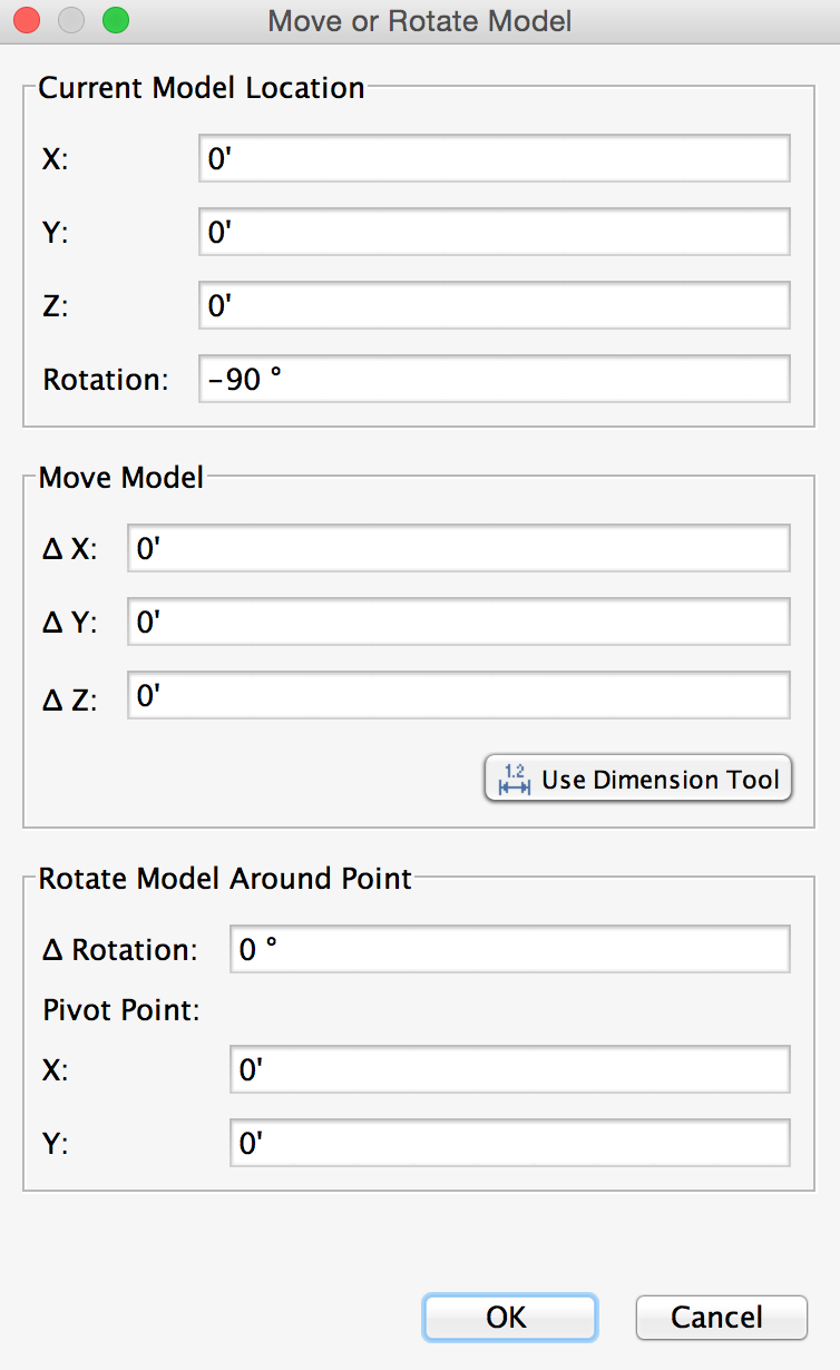
To use the “Move Model” option, if exact coordinates are available, they can be input for X, Y and Z values. In our example, it will be easier to use the Dimensioning Tool to choose two points in the model that should be exactly aligned. Select the “Use Dimension Tool” option from the Move or Rotate Model window.
Now, when moving the mouse in the 3D window, a dimensioning “Snap” tool will appear in yellow.
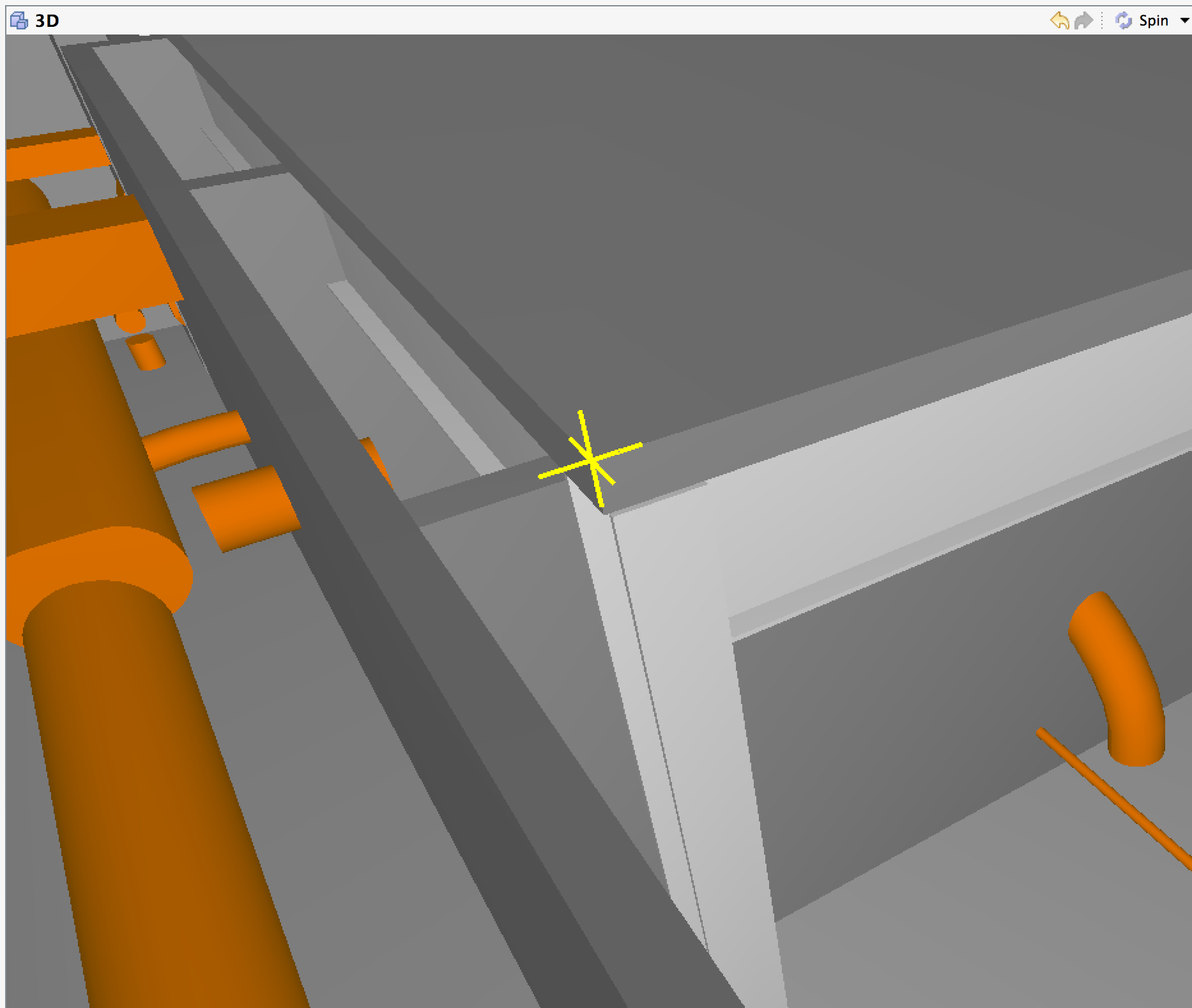
In this example, we will align the bottom surface of the roof with the top surface of the walls, and the two end corners of those components should meet. First, select the corner of the roof, then the corner of the wall.
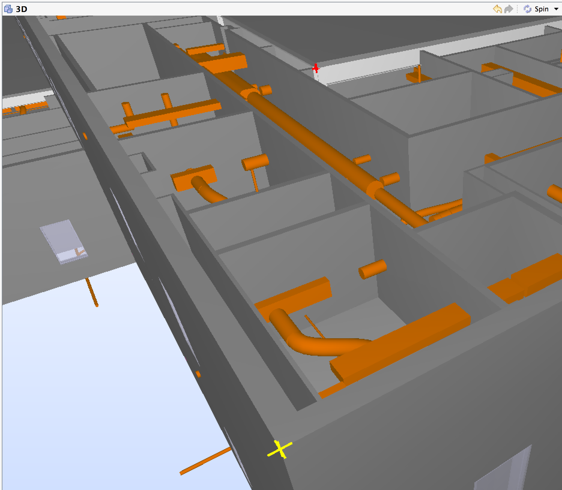
The Add Dimensions window will appear to confirm the settings. Select Ok.
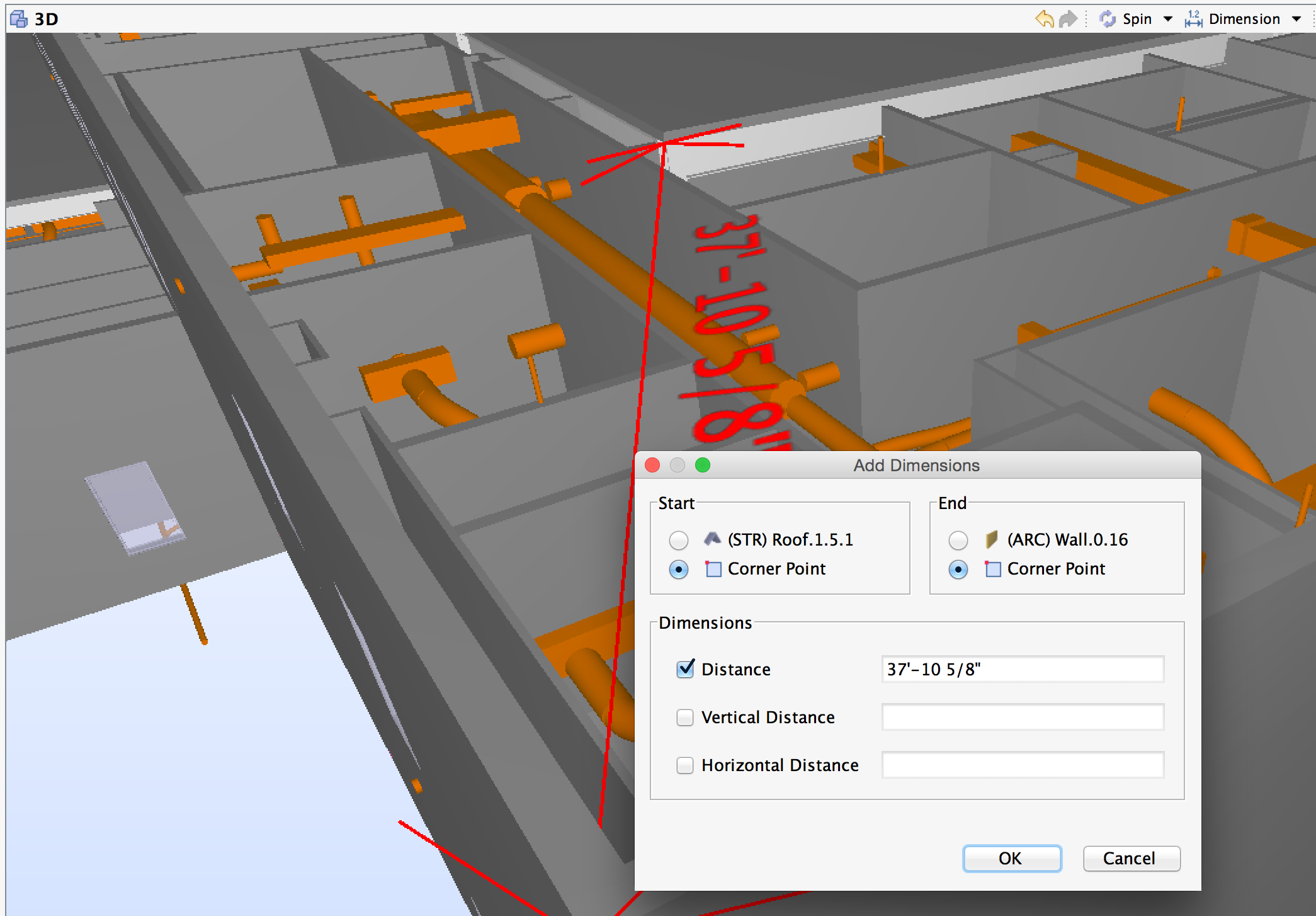
Now, Select Ok in the Move or Rotate Model window to confirm the new file coordinates and to complete the move.
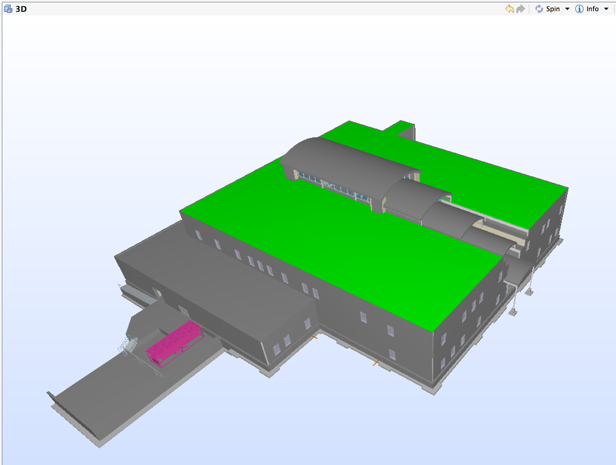
As shown below, the models are now correctly aligned.
Note: the Current Model Location now shows all changes that have occurred through the Move or Rotate Model tool. This powerful feature allows a user to see all the location information and convey these discrepancies to the designer. Then, if the designer corrects the discrepencies, you can easily revert back to the default coordinates from the IFC file.